 |
 |
last update 09/18/99
|
|
topics: magnet, generator, torque
reducing |
| project: patent: started: finished: description: |
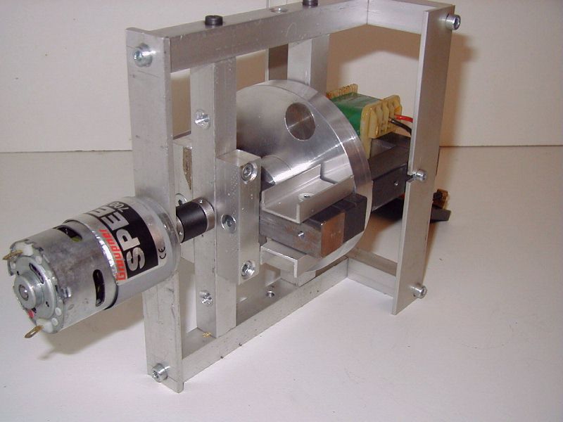
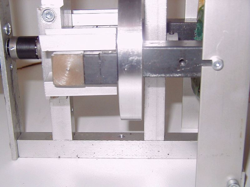
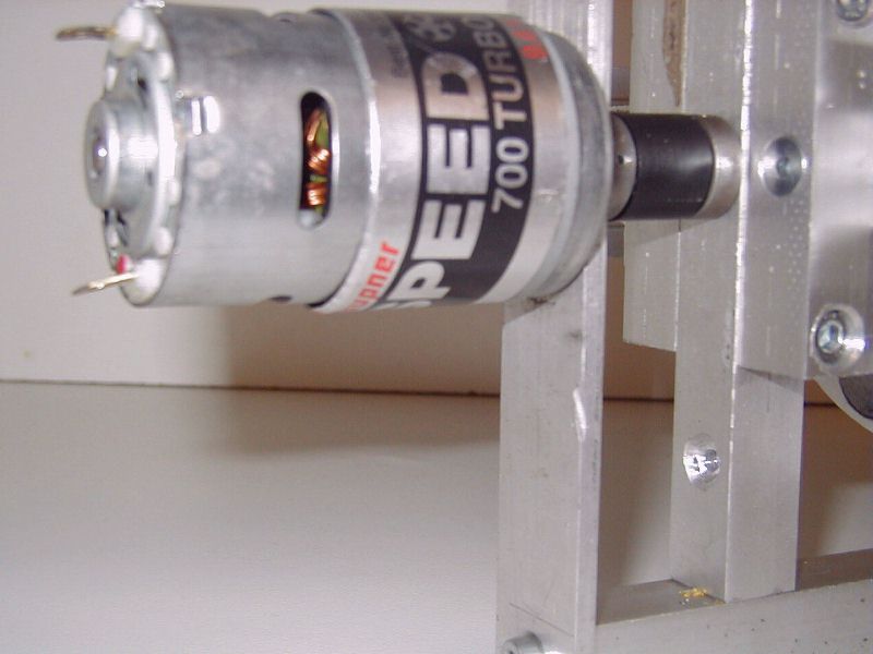
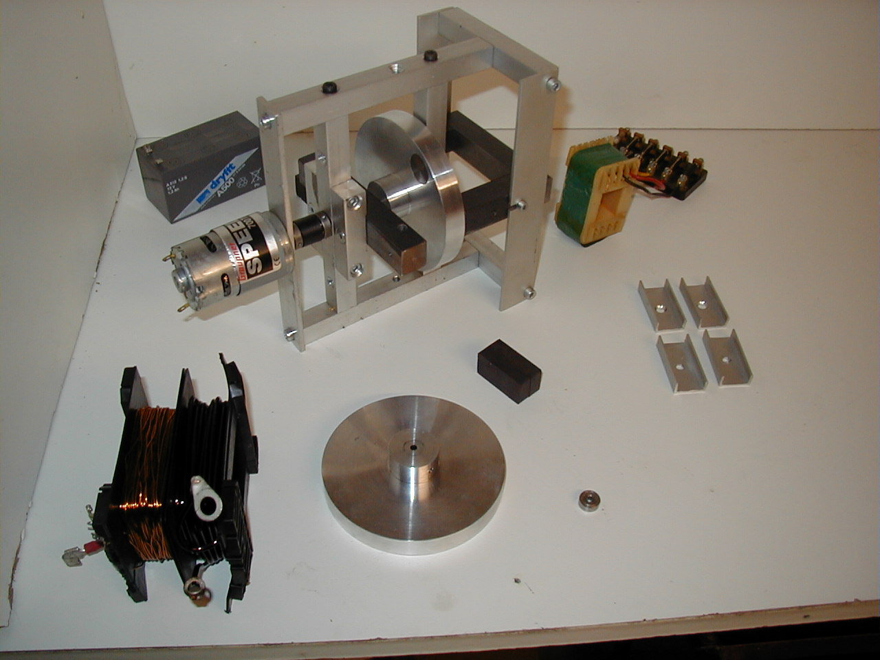
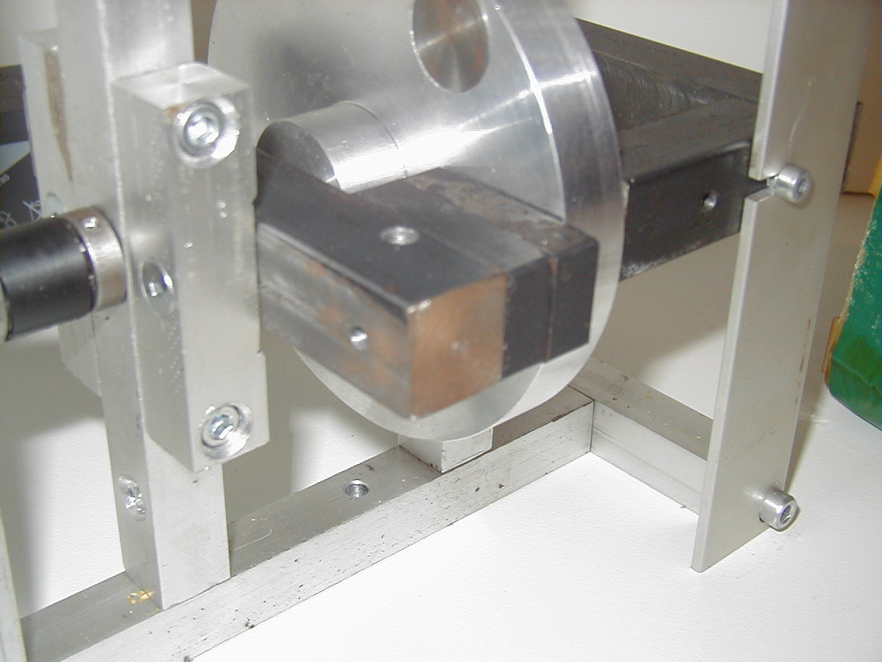
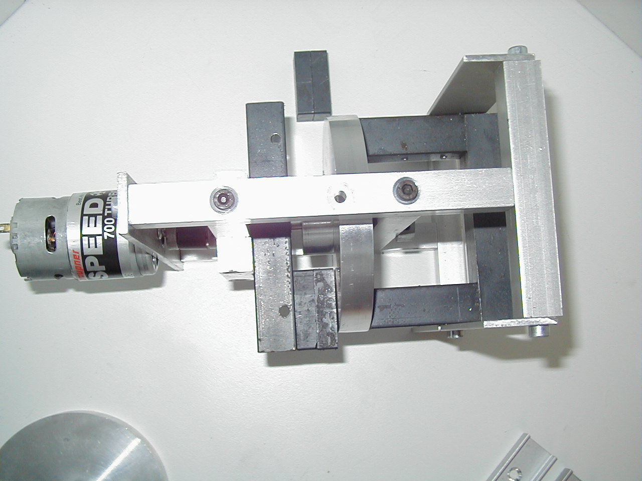
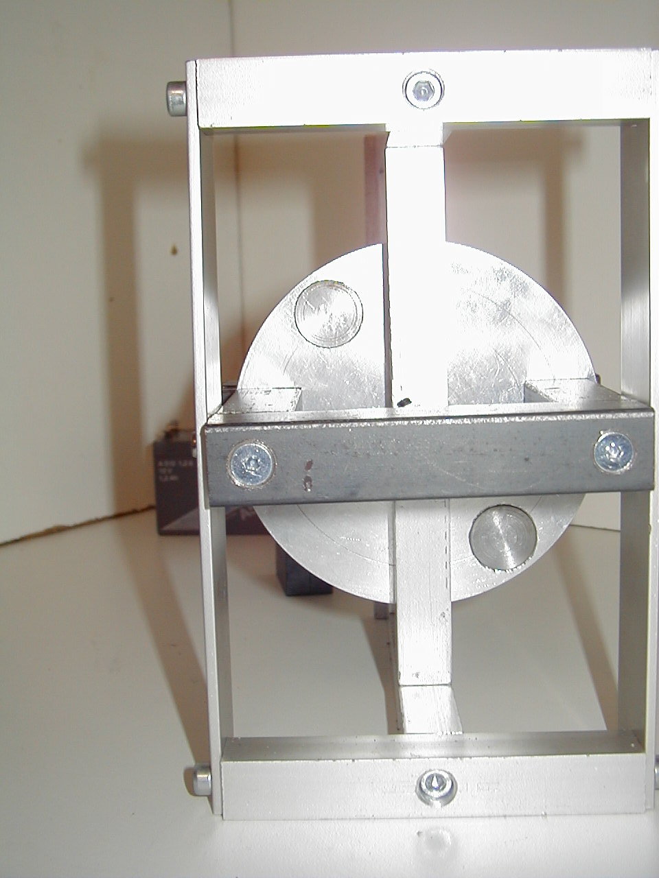
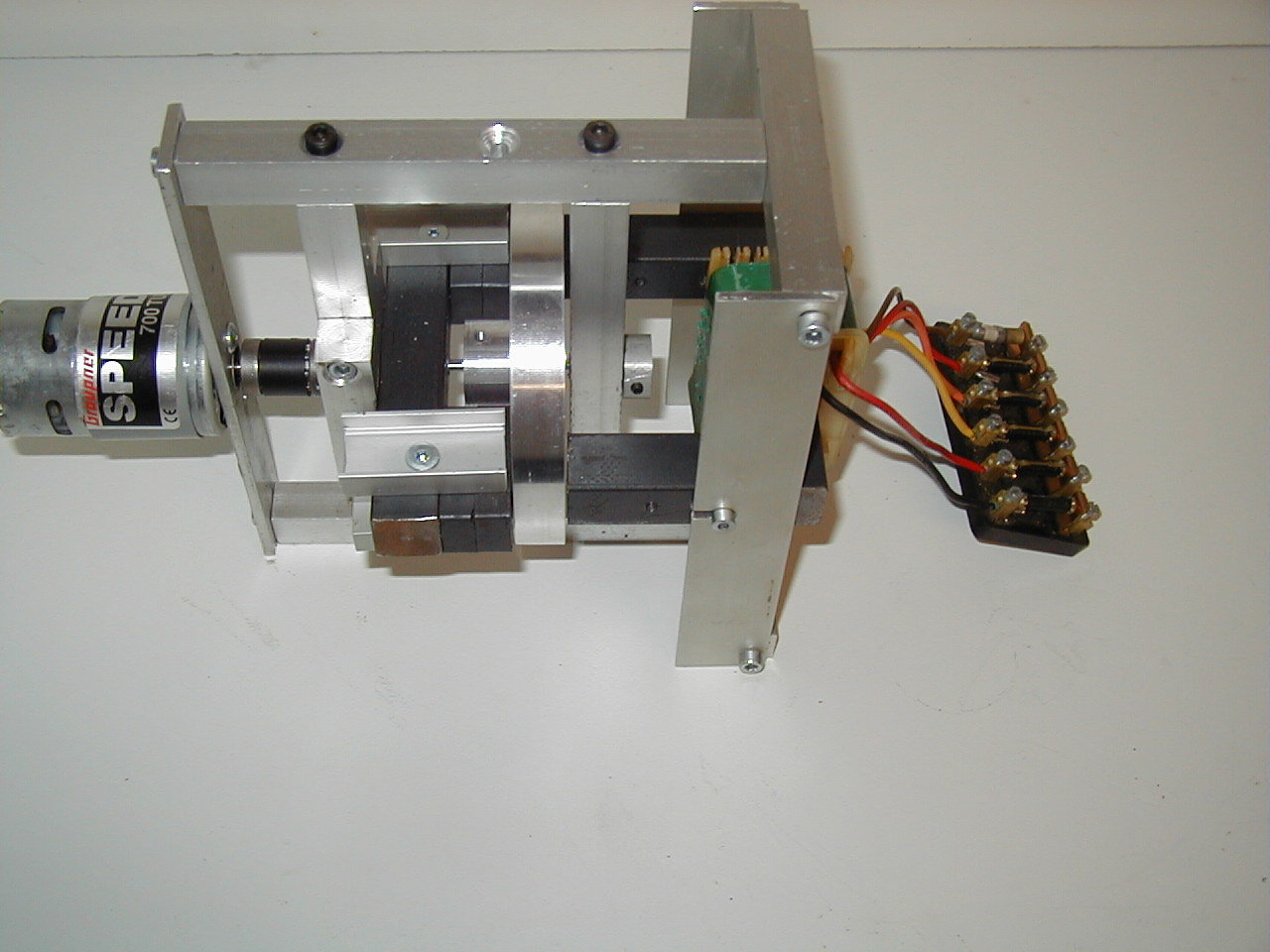
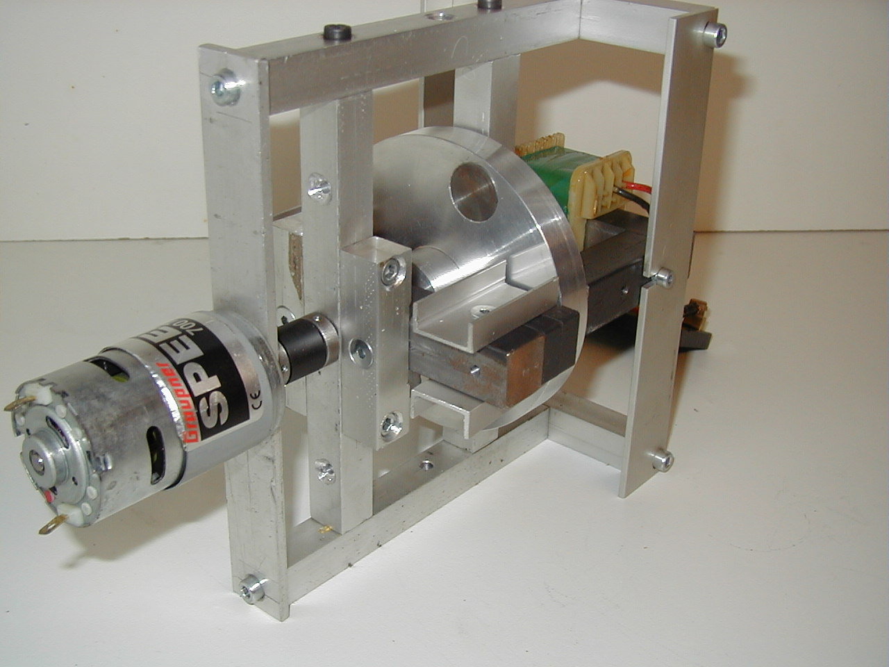
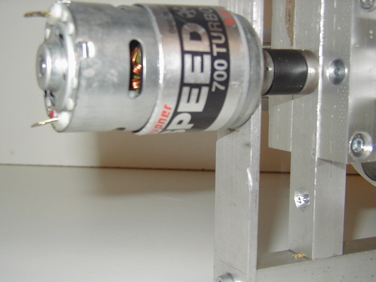
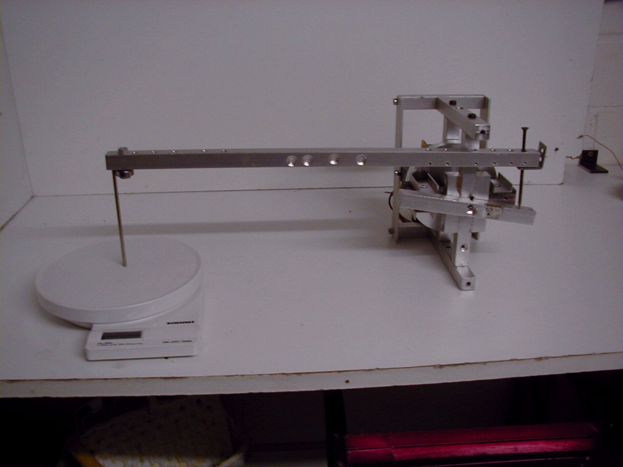
GerMagGen US5191258 - click here 08 / 1999 no as i heard about the patent from James W. German i thought for about 3 weeks about the concept and made several diagrams and drawings to understood the magnetic flux lines and field forces. after that period of theory i thought, that it is worth to invest some money and hard work at the lathe to build a prototype for first measuring tests. in august 1999 i made the rotor and some aluminium support pieces. because of urgent projects at work it took 5 weeks until i continued at the rotor design. the rotor consists now of an aluminium disc with two 20mm holes containing soft iron cylinders with 20mm diameter and 15mm length. the magnetic field is supplied from 4 ferrite block magnets 40x20x10mm. the field goes through a 20x20mm soft iron support. a standard transformator coil collects the magnetic field from this soft iron support and generates current from the alternating field strength. a standard motor (graupner, 9,6 volt, 10 ampere) rotates the disc up to 28000 upm. all other parts of the device are support. from 09/10/99 until 09/12/99 i worked 23 hours to complete the device and the first test was 09/12/99 at 03:00pm. |
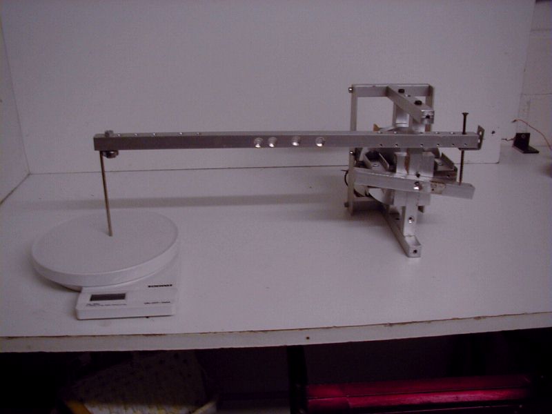
| results: | when the device is switched on, the motor uses 10
ampere at 6 volt (60 watt) with a rotation speed of ca. 3000 rpm. the best result had a coil with 38 ohm. the output was 2
volt, 10 milliampere at 100 hertz. this is not very much and because of that, it could not
be checked if the input power decreases. |
| remarks: | 3 days after the first test i had a very good idea while thinking about the device. i will not write it down here until the idea has been checked - this will take ca. 3 weeks to build a new device with different design. undependent of this new idea i will try the above mentioned enhancements and will keep you informed here. |
| pictures: |  picture 1 - overview of the device, which has not be completely assembled to be able to see some details click image for 800x600, 50kb or here for fullsize (1280 x 1024, 160kb)
if you have any suggestions, comments or enhancement ideas to this device, please mail to bitbo@t-online.de
|
| ps: | i am sorry for some typo errors and/or strange expressions, but my english is not as good as i would like - please correct me |
energy conversion systems - copyright '99 by bitbo@t-online.de |


